Engineer with Passion

SAE
FORMULA
ELECTRIC

Personal Tasks
-
Design, build, and test an electric formula racecar powertrain
-
Lead a subteam of 6 students through the engineering process, and collaborate with 60 others
-
Design powertrain aspects including sprockets, shafts, structures, bearings, press-fits, cooling, safety, etc.
-
Teach CAD and design principals to other students
-
Manage the powertrain subsystem including design & production schedule, student timesheets, budget, bill of materials, etc.
-
Present designs to sponsors to acquire advice and funding

Hard Skills
-
Solidworks
-
ANSYS
-
Solidworks Simulation
-
Computer Aided Manufacturing (CAM)
-
Computer Aided Engineering (CAE)
-
Finite Element Analysis (FEA)
-
MS Visual Basic
-
Matlab
-
CNC
-
Lathe
-
Mechanical design
-
Component-level
-
System-level
-
-
Technical presentations
-
2D drawings
-
Budgeting
-
Organization
-
Product Lifecycle Management
-
Topology Optimization
-
Vehicle state equations

Soft Skills
-
Engineering process
-
Leadership
-
Teaching
-
Teamwork
-
Planning
-
Inter and intra-organizational communication
-
Problem-solving
-
Troubleshooting
-
Collaborating with manufacturers
-
Design visualization
-
Brainstorming

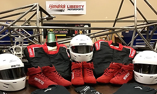
Liberty Motorsports is a racing team at Liberty University that competes in the Society of Automotive Engineers (SAE) electric formula racecar competition.
In college I spent two-and-a-half years working the hours of a full-time job to help found the team and design the vehicle's electric powertrain under the sponsorship of Hendrick Motorsports engineers.
My work involved detailed component design, system-integration of the powertrain, leadership and management, and training. These are described in great detail to show the level and quality of my work, although I still have a lot to learn!
detailed design
Sprocket Design
Because electric motors provide such low-end torque, my calculations quickly informed that a shifting transmission was unnecessary, and an optimized fixed gear ratio would suffice.
To determine the ideal fixed gear ratio I derived the equations shown which take into account drag, lift, inertia of moving components, estimated frictional losses, the motor's torque curve, and more to calculate vehicle acceleration. This equation was rearranged and fed into a Matlab program which supplied the optimal gear ratio for 0-60 mph acceleration.
A chain drive was chosen because of its rigidity and lack of stretch as compared to a belt and lack of weight compared to spur gears. Using Free Body Diagrams and ANSYS simulations I predicted the static and dynamic forces the chain must endure and selected the most efficient and lightest weight motorcycle racing chain that could meet demands.


No driving sprocket was available at our optimal tooth count and chain pitch which could also mate with the unique 6-key shaft of our Emrax motor, so I designed a custom sprocket. I used design tables to program Solidworks to generate perfect involute teeth upon user entry of pitch, tooth count, and thickness. I then designed a hub that could mount on the weird motor shaft. The mass of the new hub was to great for racing purposes, so the sprocket was machined out of titanium. A locking mechanism was also designed to work with the Emrax shaft. I performed conservative FEA on the sprocket before sending the following drawing to a manufacturer who CNC'd it in two parts and assembled them via thermal shrink-fitting. The final product is pictured below.


Structural Members
One of the most important parts of a powertrain is overall efficiency, which means a rigid structure to hold powertrain components is essential. I designed structural members using ANSYS' topology optimization. This means I intentionally over-designed the structure and let the software inform me where material was unneeded. Rigidity was emphasized more than overall weight of the structure, since the structure's mass is non-rotational and mounted to the sprung body, so its affect on acceleration and handling is minimal compared to affects of efficiency loss.
To simulate the forces in the structure, the maximum torque of the motor was multiplied by two to simulate an impulse. This represents the sudden torque upon flooring the accelerator pedal. The resulting force was then applied sinosudally to the structure in ANSYS to predict part life. My final design was predicted to withstand over 20,000 worst-case cycles and deform by less than 0.1 mm.
This rigidity at reduce weight was in part made possible by mounting the differential and motor were mounted to the same normalized steel plate so the stresses between the components were resisted by the plate which would not yield.


Press-Fits, Bearing Selection, & O-Rings
I designed a press-fit calculator that takes into account shaft and hole diameters and material properties to accurately predict the pressure of a press-fit. This allowed me to specify proper engineering tolerances for all engineering fits including press-fits, loose-fits, and transition fits depending on application. Design tables were used in conjunction with this tool to specify tolerances for bearing mounts and shafts.
When choosing bearings, I took into account as many factors as possible including bearing grade, max RPM, lubricant type, cost, tolerances (manufacturability), efficiency, bearing type, static and dynamic load rating in all applicable directions, maintenance and cleaning, etc. With plenty of bearings to choose from, it was imperative I specified the right ones for the job, and now that I've learned how to size bearings I am sure I can do it again.
O-ring selection and slot design came into play when the factory O-rings on our motor coolant fittings broke. Like the press-fits, I designed an O-ring calculator that allows users to see the squeeze and stretch of O-rings given gland size. From this I learned that the factory O-rings were over-stretched which caused damage. I specified new silicon O-rings with the appropriate temperature rating and durometer to permanently fix this problem.
Of the entire powertrain I designed or specified approximately 70% of all parts including shafts, hardware, etc. and helped the other powertrain members complete the remaining 30%.


Life-Cycle and Deformation analysis of structural members in ANSYS
Differential bearing housings designed and manufactured to transition-fit tolerances per bearing requirements
SYSTEM design
As subteam lead I was responsible for making sure the powertrain components were compatible with one another, and that the entire system was compatable with the rest of the racecar.
This meant detailed communication with the other subsystems was essential. I designed a CAD saving-and-naming convention for the entire team (see below spreadsheet) that was used successfully by all 60 members. With this system in place I was able to maintain a top-level model of the entire vehicle wherever it interacted with the powertrain (see picture). This model enabled interference detection and was easily modified when necessary.

These measures prevented major miscommunication, such as the electrical team desiring to mount an encoder where my team wanted a shaft. This detailed level of integration planning also prevented manufacturing issues, and to my knowledge no part had fitment issues throughout manufacturing.
System design also involves coming up with the overall powertrain plan. Instead of going off of convention of other teams, the entire powertrain was designed intentionally to meet our final goals. In the end my chosen rear-wheel-drive, chain-driven, limited-slip-differential design resembles a lot of teams, but that was due to calculated decision making specific to our vehicle, manufacturing abilities, and goals.

Screenshot of my spreadsheet for team part numbering
Leadership & Management
In addition to detailed and general design, my role involved a great deal of leadership including:
-
Budgeting the powertrain (we came in on-time and just under-budget!)
-
Managing the subsystem design, simulation, and production schedule
-
Delegating engineering tasks to my 6 direct-reports
-
Checking timesheets
-
Keeping the team accountable to use the naming-convention
-
Directly communicating with sponsors and our business team regarding funds and manufacturing help
-
Checking off drawings before sending them to manufacturers
-
Presenting updates to representatives from the University and Hendrick Motorsports, our largest sponsors
-
Confirming my subsystem's design was rule-compliant
Training
As one of the most experienced team members, I was responsible for training my replacements. This was done in several ways:
-
Several powertrain design training sessions with my direct-reports including small assignments by which I could check their progress
-
Directly mentoring my 6 direct-reports
-
Teaching an annual SOLIDWORKS crash-course to the entire Liberty Motorsports team
-
Filming a powertrain principals of design video for any current or future team members to watch, as well as a video on deriving equations to help with powertrain design (below). Since making the video, other teams have reached out to me via LinkedIn and I have helped in any way I can, usually by giving feedback on their math or component selection.
Powertrain Design Crash-Course
Equation Derivation Video